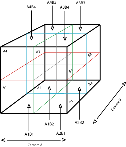
The quadrants for Camera A (A1, A2, A3, and A4) when combined with those of Camera B (B1, B2, B3, and B4) produced an invisible arrangement of 8 cubic sectors within the 3-D motion capture space.
The diagram below shows the arrangement of the eight cubic sectors resulting from the conflation of the quadrants for Cameras A & B.
|
|
The central horizontal axis of both cameras was aimed at the waistline of the dancer when they were standing upright. This allowed for the dancer to isolate their control of the music between their upper and lower bodies or avoid triggering the upper sectors all together by staying below the horizontal axis'. The central vertical axis for Camera A corresponded to the division between stage left and stage right, and the central vertical axis for Camera B corresponded to the division between upstage and downstage. Since these vertical axis' along with the border of the 3-D motion capture space and the peripheral 2-D motion capture space were invisible to the dancer (except through sound) gaffer’s tape was applied to the floor to delineate the boundary locations. The locations of the central horizontal axis' however, were left to the estimation of the dancer. By comparing the analysis from the images of both cameras it was possible to determine the dancer's general location within the eight sector cubic space (assuming they were not spiraling somewhere in the center where they might trigger all eight sectors simultaneously).
| The dancer's body is divided up equatorially by the gridlines in Cyclops (Ya-Ju Lin, dancer/collaborator). | Gaffer's tape is applied to the floor to delineate camera boundaries. |
.gif) |
.gif) |
The particular kind of analysis process used for all 128 zones (total between Cameras A&B) was a difference threshold analysis on a grayscale-converted image. Whereby if a change in the average shade value for a particular block, in comparison to the value of the same block for the previous frame, was to exceed a given threshold then a +1 value would be sent out for a shade change towards the white end of the spectrum, and a -1 value would be sent out for a shade change towards the black end of the spectrum. The threshold for the process was set just high enough that only physical motion within the motion capture space would produce sufficient changes in light values that were capable of triggering an output of values from Cyclops. Using the modular operation for quadrant differentiation (previously discussed) it was possible to track the total motion occurring over a specified period of time for a particular quadrant.
The two computers shared much of the same code for kinesthetic analysis and sector differentiation. However, Computer A was allocated the additional control function of sending a synchronization pulse to itself and Computer B every two seconds. With each new pulse the total kinesthetic activity for each sector in the past two seconds was calculated. This allowed for at least a minimum of kinesthetic activity to be recorded and used as musical information while keeping latency low enough to be relatively inconspicuous. In my experience I have found a little bit of latency actually desirable in setting music to a visual image, whether dance or film, for a variety of reasons. For one, it approximates the way we experience visual and sonic stimuli in the natural world. Another reason is that the interpretation of musical sound events is a much slower and more abstract experience compared to our instant ability to recognize visual stimuli. If the natural relationship is reversed, then the dancer would appear to be following the music and the sense of interactivity would be lost. (Enter the classic rule of effective filmscoring, the orchestra swells a moment after the kiss of dramatic culmination.)